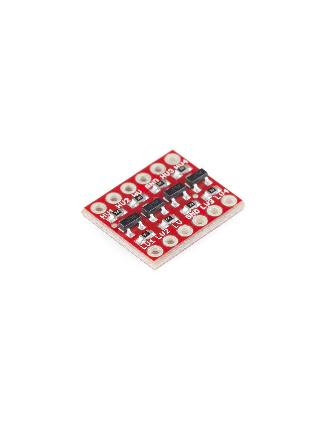
This is a small device that safely steps down 5V signals to 3.3V AND steps up 3.3V to 5V at the same time. This level converter also works with 2.8V and 1.8V devices. What really separates this Logic level converter from our previous versions is that you can successfully set your high and low voltages and step up and down between them safely on the same channel. Each level converter has the capability of converting 4 pins on the high side to 4 pins on the low side with two inputs and two outputs provided for each side.
The level converter is very easy to use. The board needs to be powered from the two voltages sources (high voltage and low voltage) that your system is using. High voltage (5V for example) to the ‘HV’ pin, low voltage (3.3V for example) to ‘LV’, and ground from the system to the ‘GND’ pin.
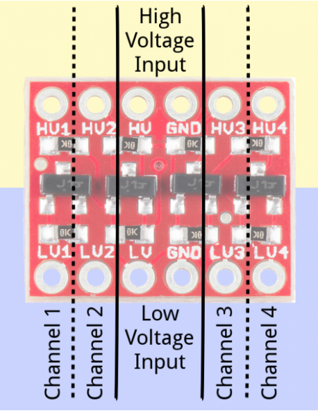
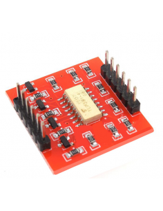
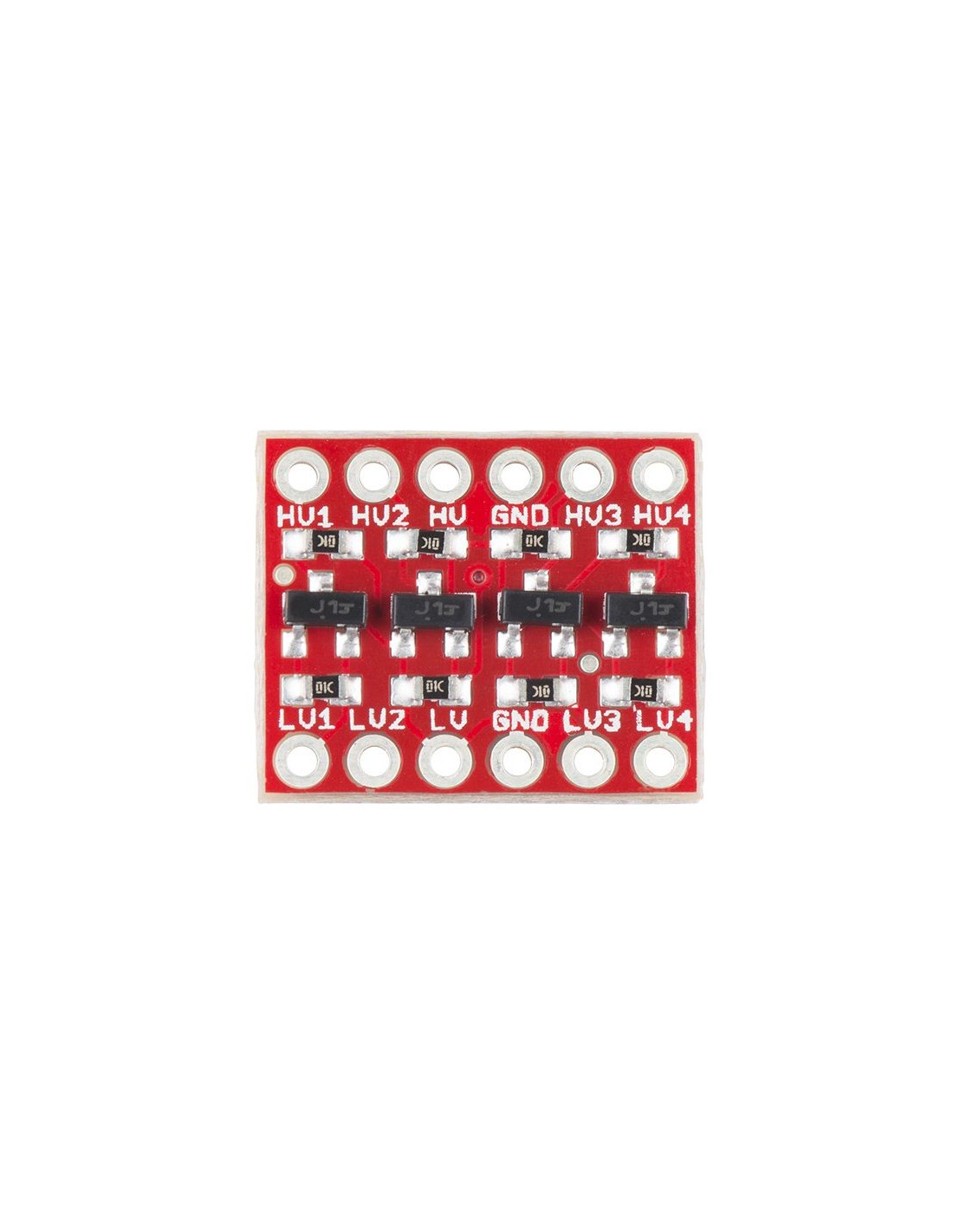
Pin Layout:
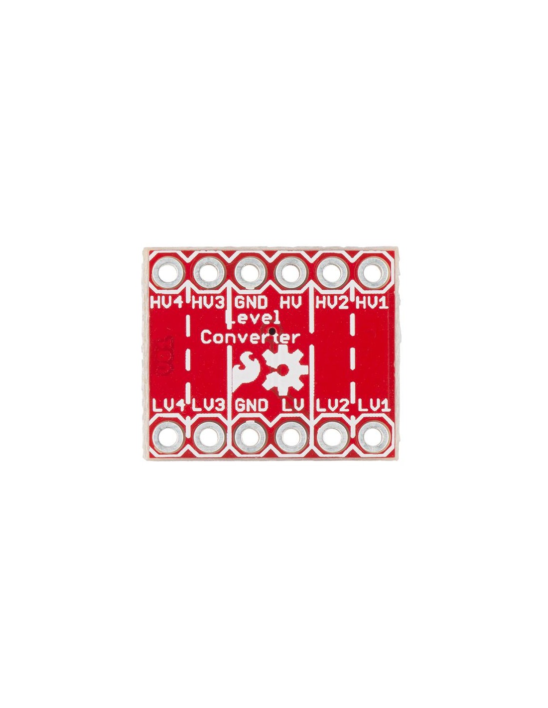
There are 12 total pins on the BD-LLC -- two parallel rows of six headers. One row contains all of the high voltage (e.g. 5V) inputs and outputs, the other row has all things low voltage (e.g. 3.3V)
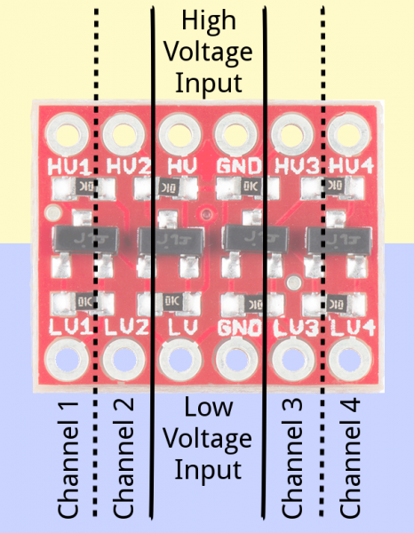
The pins are labeled on both the bottom and top sides of the board, and organized into groups. Let's look closer at some of the pin groups:
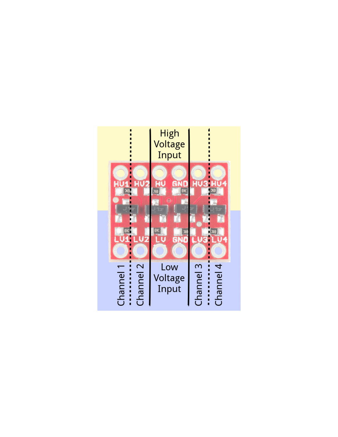
Voltage Inputs:
The pins labeled HV, LV, and two GND's provide high and low voltage references to the board. Supplying a steady, regulated voltage to both of these inputs is required.
The voltage supplied to the HV and GND inputs should be higher than that supplied to the LV side. For example, if you're interfacing from 5V to 3.3V, the voltage on the HV pin should be 5V, and the voltage on LV sould be 3.3V.
Data Channels:
There are four separate data channels on the BD-LLC, each capable of shifting data to and from high and low voltages. These pins are labeled HV1, LV1, HV2, LV2, HV3, LV3, HV4, and LV4. The number at the end of each label designates the channel of the pin, and the HV or LV prefix determines whether it's on the high or low side of the channel.
A low-voltage signal sent in to LV1, for example, will be shifted up to the higher voltage and sent out HV1. Something sent in HV3 will be shifted down and sent out of LV3. Use as many of these channels as your project requires. You don't have to use every single one.
Keep in mind that these level shifters are purely digital. They can't map an analog voltage from one max voltage to another.
Assembly:
Before you can plug the converter into your system, you’ll need to solder something into it. There are a lot of options here. You could solder straight male headers in, and plug it right into a breadboard. Or perhaps you want to solder wires directly into it. Pick an assembly method that suits you best with how you intend to use the board.
Once your BD-LLC is soldered up, it's time to hook it up. Your hookup will probably vary depending on which communication interface you're using.
Please see the below link on how to connect the level converter for three of the most common communication protocols:
Logic Level Converter Bi-Directional R2


